

Laing DDC 3.2 (MCP 355) Pump Top Test Comparison - 11 Tops Tested!
Introduction
Welcome to my multiple pump top and reservoir top shootout. Over time I’ve acquired the necessary tools and techniques needed to fully test pumps. The DDC 3.2 is Laing’s newest revision of the extremely popular DDC pump, also rebranded as the Swiftech MPC355. This pump comes with a stock top that is designed with 3/8” fittings and the inlet barb has a sharp very small diameter 90 degree bend. Overall the pump’s design is really ideally configured in power and pressure orientation for today’s water cooling systems. It’s almost the perfect water cooling pump, good power/heat dump ratio, good pressure capabilities, nice compact size. Unfortunately the stock top only comes with 3/8” barb fittings and that sharp 90 degree inlet bend looses a fair amount of efficiency.
Along comes the aftermarket tops.....straightening out that inlet and providing the much more desireable G1/4 fitted barb. Unfortunately there is not alot of performance related data on the existing tops. I'm a bit of a measurebater and like to know which performs better, and since I have the tools to test them, I figured, why not? I’ll ask around and gather up as many as I can and test them all on the same pump and give the community some real comparative data. My ultimate hope is that this will encourage a few tweaks and we'll even have better tops to choose from later...win win!!
Testing Sponsors
 Coolmiester (XS member name) of Coolercases UK - Please visit their website and forums. They provide a great resource to the community and wide range of products. Coolmiester sent me the following loaner samples: Petra's DDCT-01s Top, EK-DDC X-Top G1/4, EK-DDC X-Top G3/8, Alphacool DDC plexitop, and the Alphacool DDC Plexi Reservoir. Five of the testing tops, thanks a bunch, very much appreciated!
 Petra of Petra's Tech Shop - Provided me with a loaner sample of the Koolance DDC top. Since I already had a a DDCT-01s top, they offered and sent me the Koolance top they had from thier own testing. Petra's Tech shop is my #1 pick for shopping in the USA, they are like the newegg of water cooling for us USA folks, only 10X the customer service. I particularly encourage you to shop there, because they are also truely committed to testing and finding out the truth about water cooling products. That means worlds to me and I order stuff from them all the time. How many Petra pens do YOU have?...:)
 Paul from XSPC provided me with both the XSPC Laing DDC top and their newly release XSPC Acrylic Reservoir DDC Top product samples. A UK based company with some very refined performance products.
 Jeremy from Danger Den provided me with a sample their Danger Den DDC acrylic top. Danger Den is another great manufacturer and reseller of all type of water cooling products, based here in my home state of Oregon in the USA. As you'll see in many of my other reviews they are very committed to producing products with good flow rate capabilities. I've really enjoyed reviewing many of Danger Den's products, they are great folks that manufacture great products!!
 Gary from Sidewinder Computer Systems provided me with an OClabs sample. I shop at Sidewinder very regularly and highly recommend you check them out. Sidewinder is also committed to providing various forum members gear to test, and very committed to supporting forum members in their testing adventures. They carry a wide range of water cooling gear at the very best prices!
 Rob from the Watercoolingshop.com provided me with the EKG3/8" Barbs for the EKG3/8" X-Top. He also provided these nice G3/8" to G1/4" adapters which I used in some recent radiator testing. They have a wide variety of water cooling gear and specialize in water cooling parts. I highly recommend them!
| NaeKuh (XS member) | Another very active member in the water cooling comminuty always out to try new things. I've been building him a TEC chiller and while I was at it he sent me his EK X-Res 140. Unfortunately I sent this sample back to him before I retested all the samples measuring total head, so I do not have that result. |
The Pump Used for Testing - Swiftech MPC 355 (18watt), or Laing DDC 3.2
The pump I used in all of this testing is one that I recently purchased at Petra's, it is the newest iteration of this popular little hard working pump. Very possibly the most popular pump out there for water cooling. So $75 bucks later along with Petra's amazing customer service, I had a happy little pump sitting on my test bench. I happened to be a long time Swiftech MPC655 (Laing D5) vario user, so it was fun trying out this new little pump. The older and more powerful DDC2 is no longer in production, while performing better it also had some proplems with pump failure. So far this new DDC 3.2 pump appears to be doing much better, I havn't heard very many problems with it, and it appears to be a completely redesigned pump. Anyhow, I'm not here to talk about the pump specs, there's plenty of that available on the internet, but I've linked you to some good articles down below here. It's a very good and popular pump. Swiftech's website on the MPC355 -They rebrand this pump and include their own accesory package.
Laing's website for the Laing DDC3.2 - They manufacture this pump. DDC3.2 brochure.
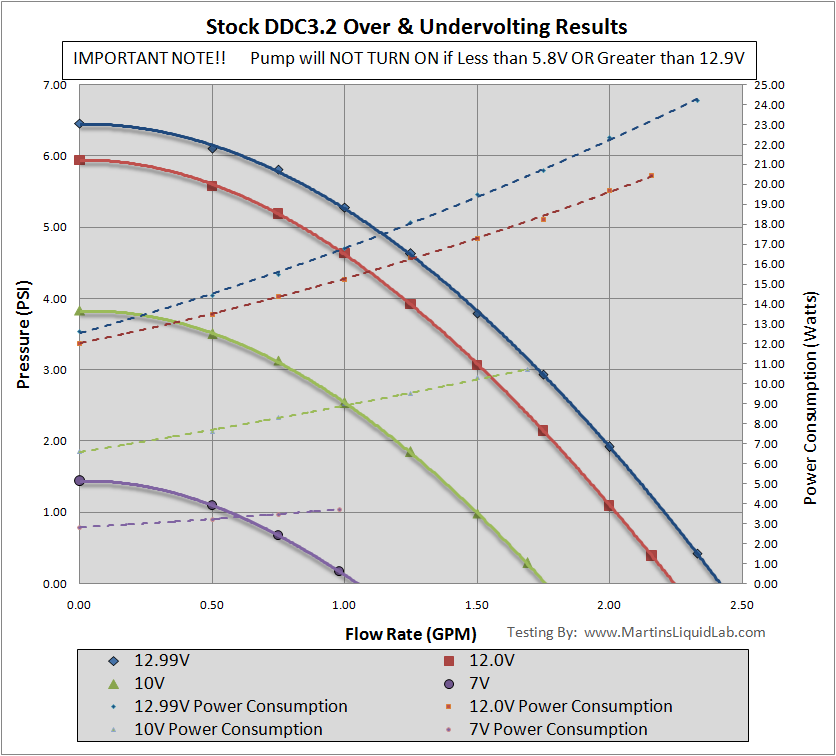
One little bit I would like to add before I go on to the tops is a little testing I did with the stock pump to explore over/undervolting potential. In the end I found that you get some decent gains from overvolting and you can really turn the pump down ALOT undervolting. Unfortunately it's a little scary because exceeding some very defined limits will not allow the pump to start. It appears there is some sort of protective circuitry built into the pump to prevent you from overvolting the pump very much. I found that limit to be around 12.95 to 13.00 Volts and it was a limit on startup only. I could start the pump at 12.00V and turn voltage up to 13.5V, but after turning off my PSU and trying to start it at 13.00 more, it simply would not start. This could be a very bad situation if you were overvolting to 12.9V and just happend to have a surge of power that resulted in your pump not starting because your PSU surged and produced 13.0V!... Up to you if you want to overvolt, but it definately has some risk (possible failure to start and overheating). I'm not very experienced in ATX power supply specifications, but I know my current PSU(OCZ GameExtreme 700) actually produces around 12.4V on average, so the 12.9V limit is probably designed to give just enough room for differences in your average power supply, very little extra. Not sure it would be worth the extra .1GPM, and if you wanted to undervolt you could modify the DDC3.2 to be a DDC 3.1 by removing the soldered bridge. DDC3.2 VS DDC3.1 Photo Difference
Performance Measurements
P/Q (Pressure Vs. Flow Rate Curves)
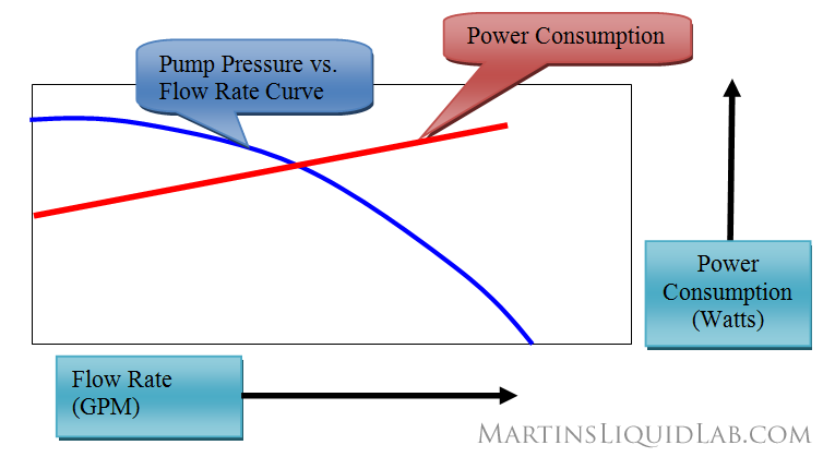
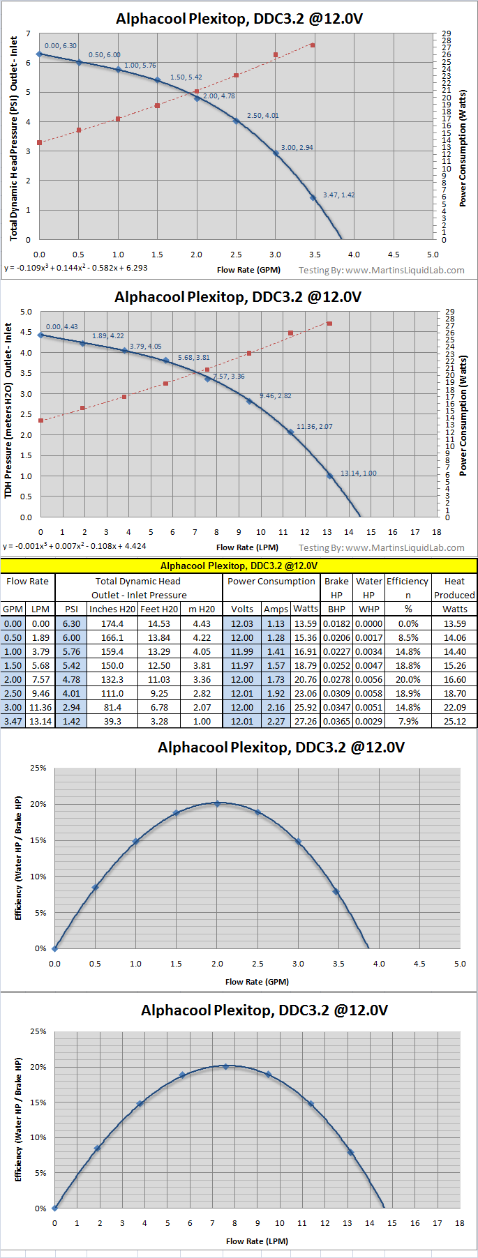
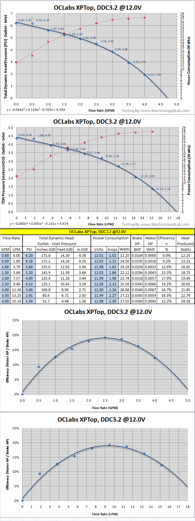
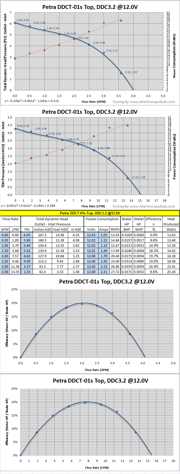
First and probably the most important is the ability to measure a pump’s PQ curve. You’ve probably read in your own pump specs two general numbers that are specified. One is typically the maximum head or lift. The second is the maximum flow rate. These two numbers are two points that are part of this curve. PQ stands for P being pressure and Q being flow rate, so in the end it’s just a curve that represents the relationship of pressure and flow rate.
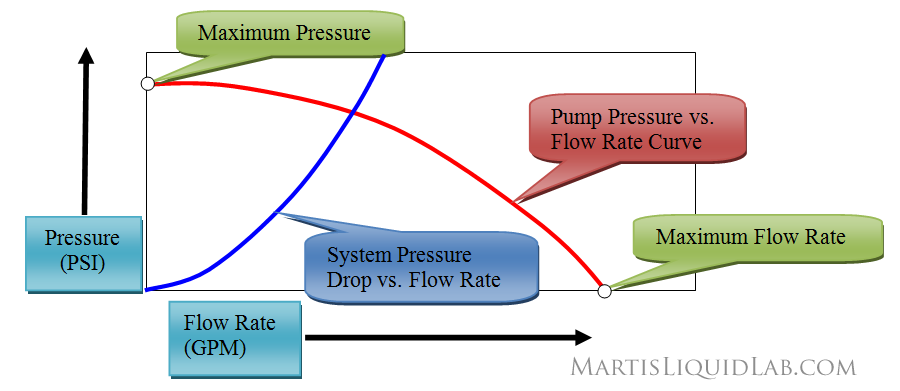
Unfortunately these two numbers or points on the curve only indicate points of value where our pumps never operate under a real water cooling system. Maximum flow only occurs when there is absolutely no resistance. And maximum pressure only occurs when you’ve completely stopped the flow (pinch and kink your tubing, now you have max pressure, but zero flow). Furthermore they do not provide you with information about the curve or path in between these two points (The results will show you how important curve "shape" is as indicated by the DD top". There are all types and shapes of this curve and it’s critical to plot the entire curve and particularly look at the range between 1 GPM and 2.5 GPM because this range is where the system pressure drop curves typically intersects the pump curve. Where these two curves intersect is what determines your water cooling system flow rate. So pressure vs. flow rate is “The” ideal measurement of pump performance that determines flow rate. After collecting this data, I’ll evaluate these curves where it is important and explain what they mean in more detail.
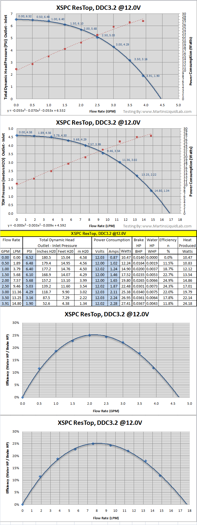
Update 4-5-08 Total Dyamic Head (Outlet - Inlet) Water Pressure Measured
In the past all of the pump testing I have seen in watercooling has generally only measured the outlet nozzle of the pump (Outlet/Discharge Head Pressure),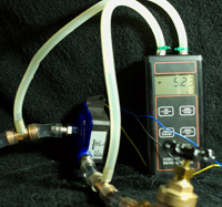 however after running this series of tests I became increasingly interested in why some of the reservoir tops had a performance advantage. After further research I discovered that to capture the full power of a pump, it's important to measure pressures as the suction side of the pump (Inlet/Suction Head Pressure). In the end, the energy provided by the pump comes in two primary forms, pressure differential and flow rate. To measure pressure differential or Total Dynamic Head of a pump you take the outlet pressure and subtract the inlet pressure. A dual input manometer which I use is ideal for this testing as I can simply install a pressure sensor Tee fitting at both sides of the pump and read a direct pressure gain across this pump. The relative comparison between the tops is very similar in my net end result, but the overall power improvement will make some difference in flow rate calculations and in the end it's also the proper way to test pressure on a pump. So from this point forward, I will be testing pumps and measuring "Total Head" instead of just "Outlet/'Discharge Head".
Power Consumption vs. Flow Rate
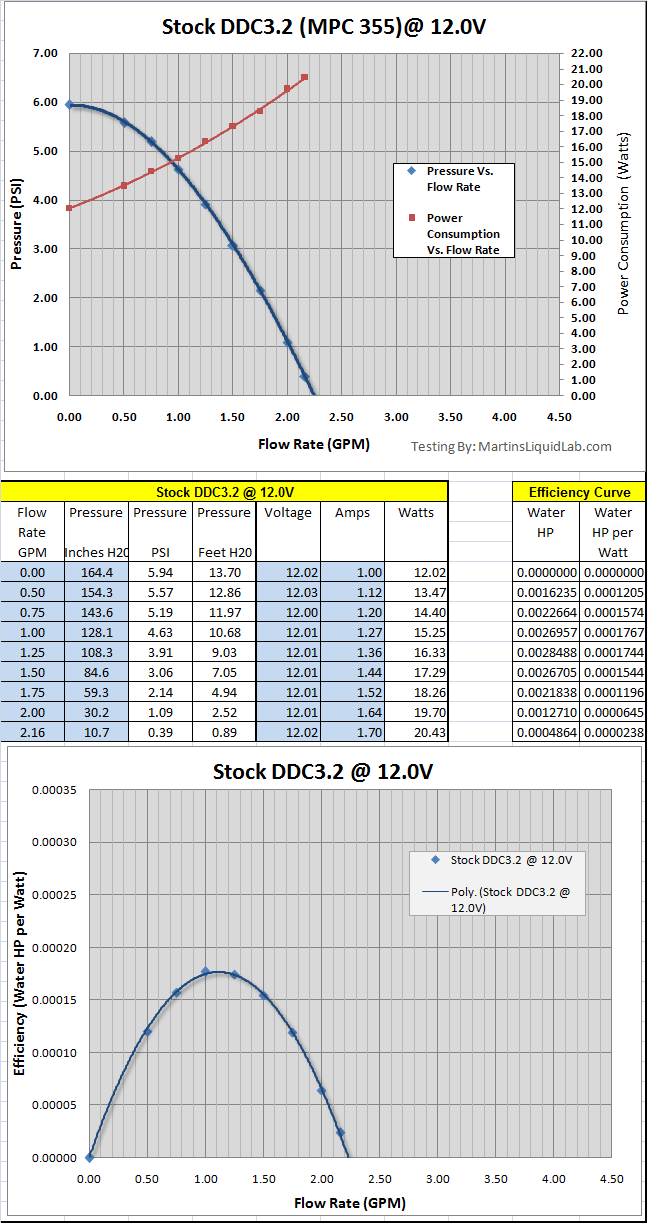
In addition to measuring pressure and flow rate, I also collected the pump power draw in terms of voltage and current (amps). Voltage was necessary to ensure a proper 12.0V being fed to the pump anyhow, and it’s very easy to add another multi-meter in to measure current. This provided me with the ability to measure how many watts were being drawn by the pump at each test point. This information is not particularly important in comparing tops using the same pump motor, but it is EXTREMELY important in pump selection because a large percentage 60-90% of the pump power consumption is dumped into the water cooling loop as HEAT! The added benefit of collecting this information is explained later with efficiency comparisons.
Efficiency (Updated 4-5-08)
In addition to providing the two above performance measures, I also wanted to provide some sort of means to measure efficiency. This is a measurement of water horsepower to break horsepower and simply shows you where the pump and top combination peaks in efficiency. Smaller pumps generally have lower efficiencies, but this does at least provide you with how efficient each top is and where they peak in flow rate. On pump selection ideally you would select a pump that peaks in efficiency where your system flow rate resides, but that's more of a criteria engineers use when selecting large pumps. What I did find interesting is that many of the pump tops peaked in efficiency at flow rates higher than typical.
The DDC 3.2 Pump Top Contenders
The following alphabetical list of pump tops were included for testing:Alphacool DDC plexitop
Alphacool DDC Plexi Reservoir
Danger Den DDC acrylic top
EK-DDC X-Top G1/4
EK-DDC X-Top G3/8
Koolance COV-PMP01P
OClabs XP-Top
Petra'sTech DDCT-01s Acetal Top
XSPC Laing DDC top
XSPC Acrylic Reservoir DDC Top
Stock DDC3.2 or MPC355 Pump with stock top
Testing Equipment and Methods
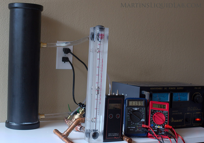
Note the above photo is the old test method of outlet discharge pressure only, all tests have been redone to include Inlet pressures.
Pressure – Dwyer Series 475 Mark III digital manometer. – Measures differential pressure, calibrated zero in setup at zero flow rate. Note this corrects out Atmospheric pressure (not PSIG), and it also corrects out static pressure from the test loop. In the end this is a true measurement of pressure added by the pump with atmospheric and static pressure errors removed. Accuracy.5% of FS or 1” H20 per manufactures specs. In testing, the actual pressure fluctuates typically 3-4” H20 at high pressure down to about 1” H20 at lower pressures. In the end, I would estimate overall operating pressure to be accurate to about 1. to.2psi
Flow Rate – King Instruments 0 - 5 GPM, 250mm scale 7520 series flowmeter. – Accurate to 2% of FS, so about.1GPM per the manufactures specs
Voltage and Current – Standard multimeters were used, one was connected in parallel for measuring voltage, and one in series on the power line to measure current. These are not scientific grade meters, but accurate enough for these purposes. Comparing several multimeters, voltage between them was accurate to within about .05V.
DC Power –
Custom 4" x 24" reservoir –
.25 GPM record interval - I recorded data starting at .5GPM in .25GPM increments until the pump maxed out flow rates and my gate valve was completely open.
Test Fluid is Plain Cold Tapwater - Standard cold tapwater was used for all testing. In between test runs, the system was drained and cold tapwater was used to refill the system. Our household water is clean treated drinkable and the specific gravity very close to 1.0 and viscosity of negligible difference. Someone may wonder why I didn't use distilled water, and I could have, but considering a water cooling system is typically going to have ethelene glycol or some other coolant mixture of addatives, I figured the very minor amounts of chlorine added to our drinking water is insignificant in comparison. Besides this is a relative comparison and all tops are tested with the same fluid so any error would be reflected the same in all tests.
Top Mounting - All tops were mounted with the same amount of torque and pressure which is a fairly snug fit. But before doing so I carefully inspected the alignment of the top to the alignment of the impeller inlet. The DDC tops were all capable of shifting around 1-2mm, and I felt it was important to get a perfectly centered inlet for each test.
Pressure Vs. Flow Rate Curve Comparison
First up is the entire curve, and the area to note is in between the two red system curves. The left most limit would be an extremely high restrictive system and to the right would be an extremely low restrictive system.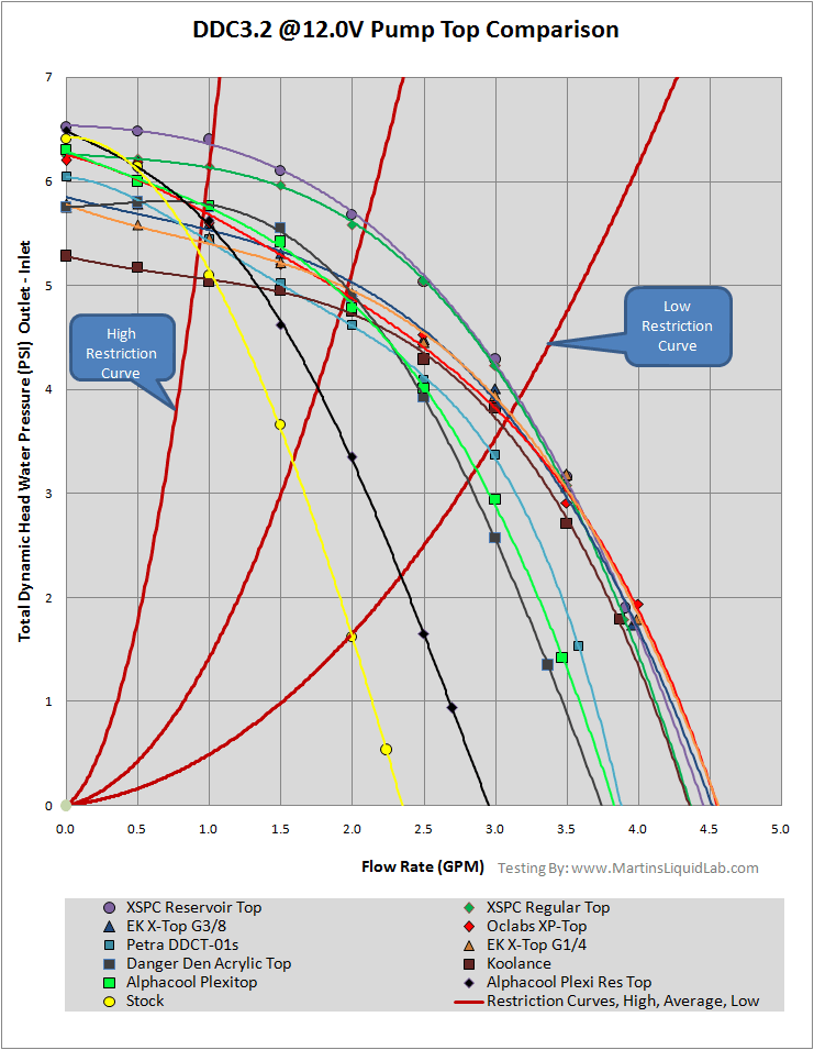
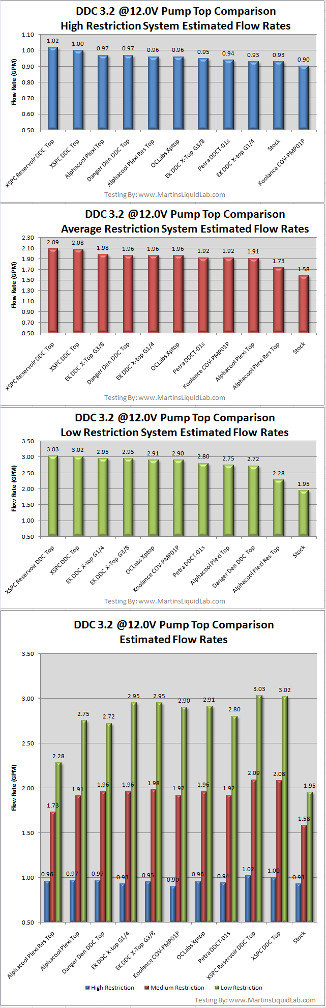
Estimated Flow Rates
If the above curves are difficult to understand, I've extracted the following flow rates for a relatively high restriction system, average restriction system, and low restriction system:High Restriction System = Fuzion w 4.5mm Nozzle, Fuzion GFX, HWLabs 480GTX, Reservoir, 7' 7/16" ID Tubing
Average Restriction System = Swiftech Apogee, Swiftech MCW-60, Hwlabs BIX 360, 5/8" Tee, 7' 7/16" Tubing
Low Restriction System = Danger Den MC-TDX, PA160, 5/8" Tee Line, 7' 7/16" Tubing
Side Inlet Performance
I would not recommend using the side inlets unless you absolutely have to.
Conclusion
The XSPC tops are performing the best in all system configurations, a true tribute to the design and tweaks that have occured in the current design...excellent!!
The remaining tops all perform very well and have trade offs between each other depending on the system restriction. Some are slightly more tuned lower flow rates and others for higher flow rates.
In the end, these tops can afford you as much as 1.08 GPM gain on low restriction systems, .51 GPM on an average restriction system, and .12 GPM on extremely high restriction systems..... that's a good flow rate gain!!
| Description | Detailed Test Report |
Inlet Dia. mm |
Outlet Dia. mm |
Volute Shape |
Volute Depth mm |
Reservoir Bleeding Performance |
Barbs Used | General Notes |
Alphacool DDC plexitop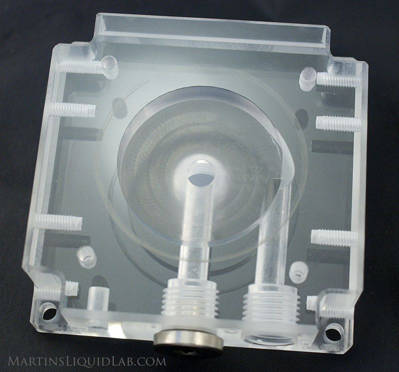 |
 |
6.90 | 7.0 | Circle With Relief Cut |
7.9 | N/A | D-Tek | Machined Acrylic Center Inlet |
Alphacool DDC Plexi Reservoir 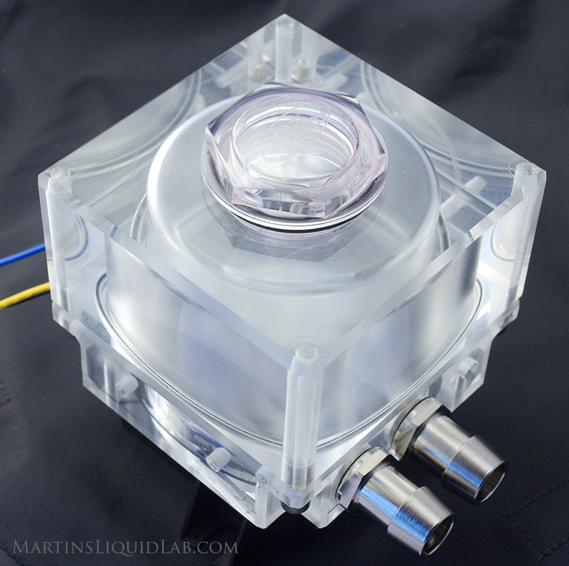 |
 |
6.90 | 7.0 | Circle With Relief Cut |
7.9 | Average, Noted votexing at low fill and at low flow/high resistance (.5GPM) | D-Tek | Machined Acrylic Side Inlet |
Danger Den DDC acrylic top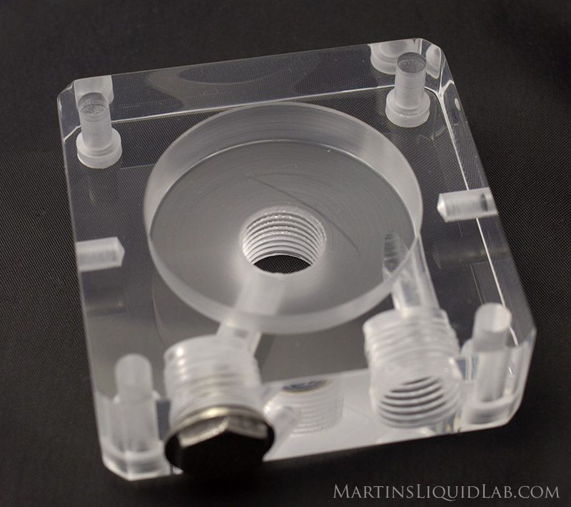 |
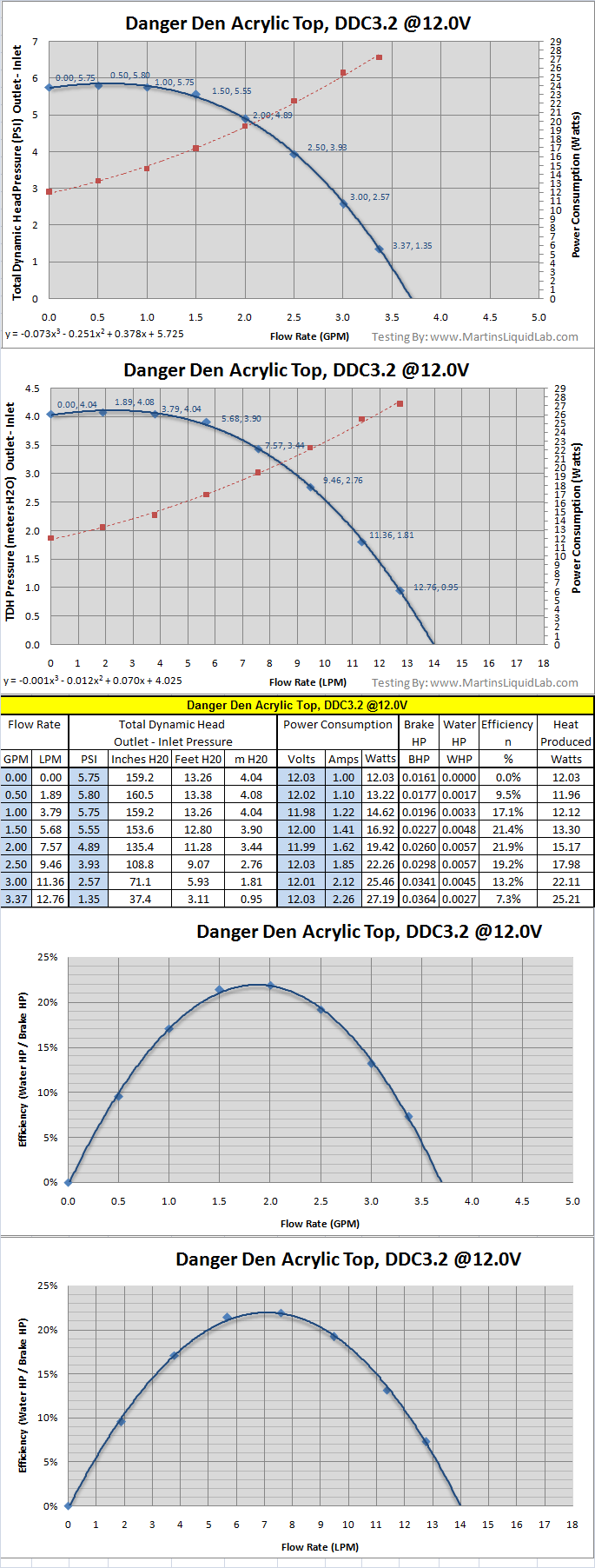 |
12.00 | 5.75 | Circle | 8.5 | N/A | DD Fatboy G1/4 |
Machined Acrylic Center Inlet |
EK-DDC X-Top G1/4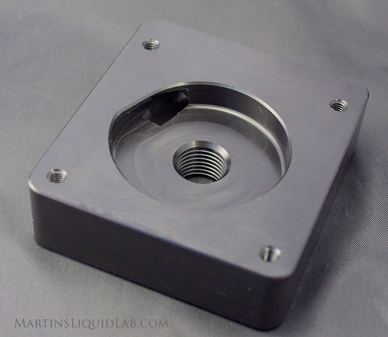 |
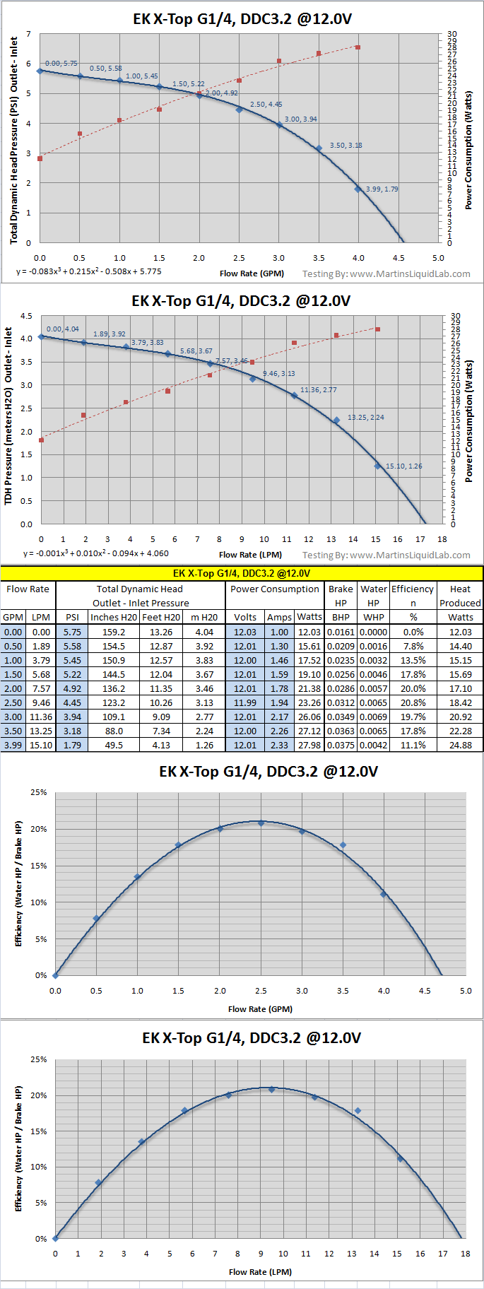 |
11.69 | 8.3 | Semi Spiral |
7.6 | N/A | EK G1/4 | Machined Delrin Very Nice Finish! |
EK-DDC X-Top G3/8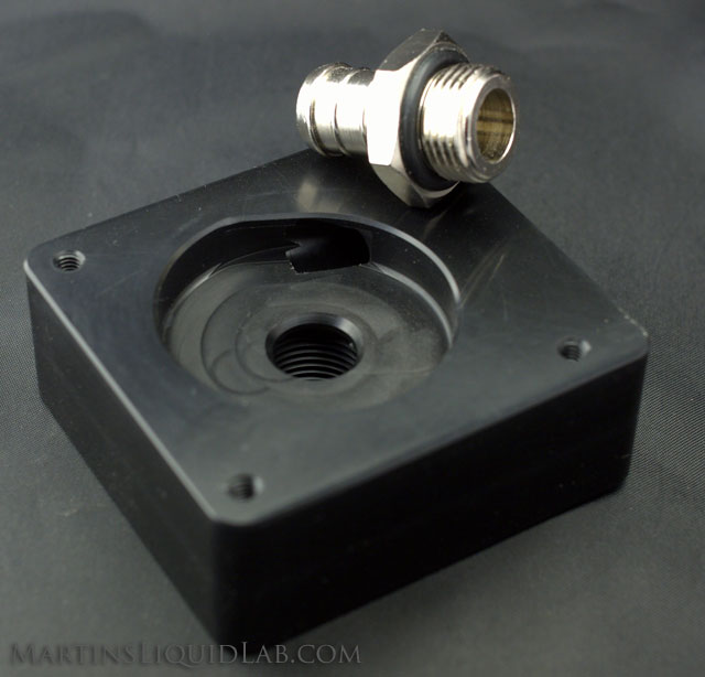 |
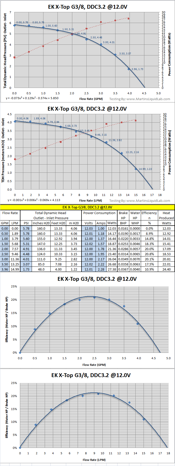 |
11.55 |
8.2 |
Semi Spiral |
7.7 |
N/A | EK G3/8 | Machined Delrin Very Nice Finish! |
Koolance COV-PMP01P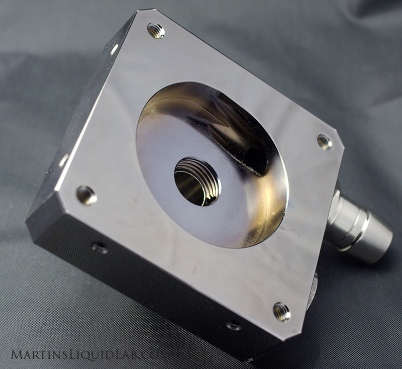 |
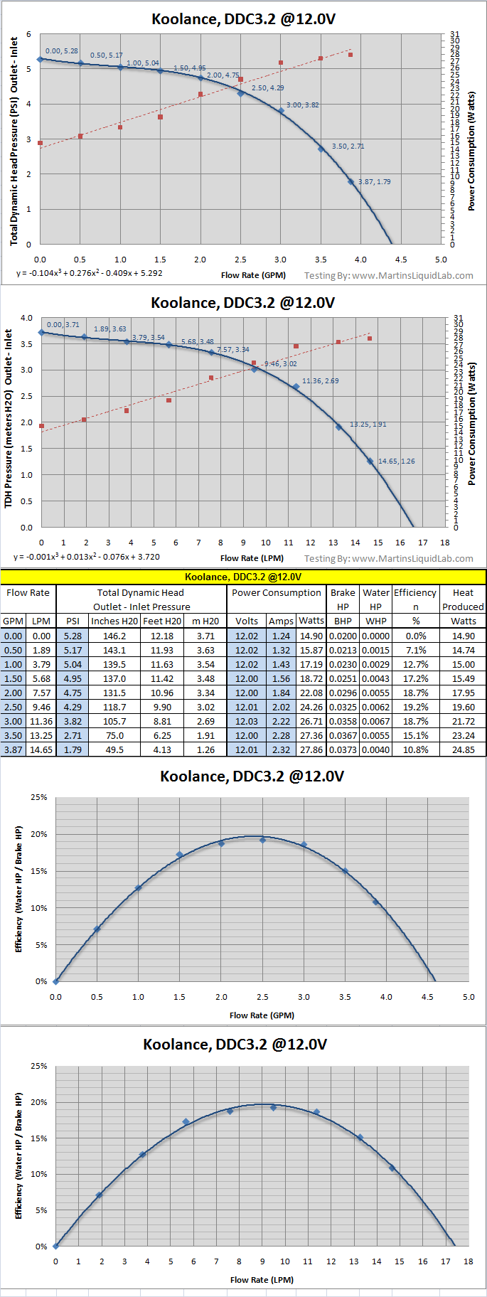 |
11.88 | 7.66 | Semi Spiral |
8.2 | N/A | D-Tek | Center Inlet. Large step loss in dual outlet. Aluminum!!! Used D-Tek Barbs. |
OCLabs XP-Top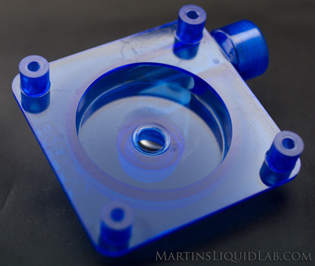 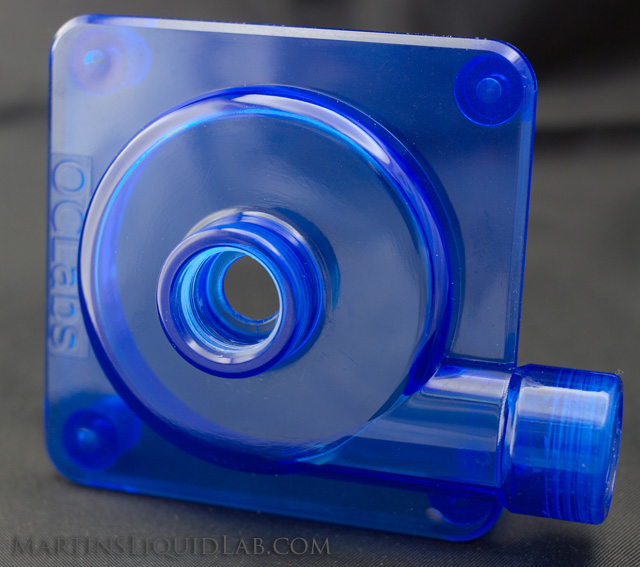 |
 |
7.9 | 10 x 6mm Rect. |
Circle | 7.9 | N/A | XSPC D-Tek Too Long for Inlet |
Injection Molded Acrylic. Coarse Threaded screws. |
Petra'sTech DDCT-01s Acetal Top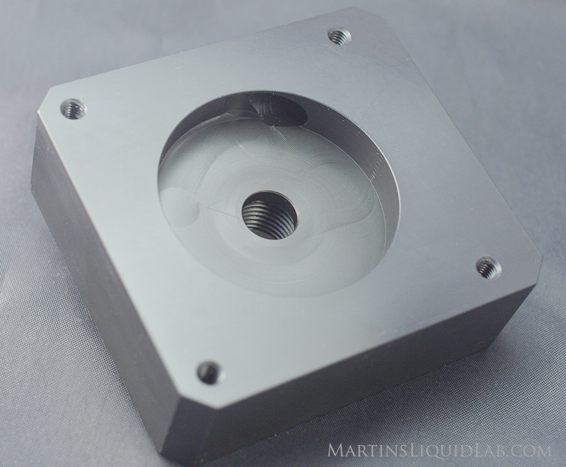 |
 |
9.50 | 7.00 | Circle With Relief Cut |
7.9 | N/A | Acetail/Delrin Very Nice Finish! Used D-Tek Barbs |
|
XSPC Laing DDC Top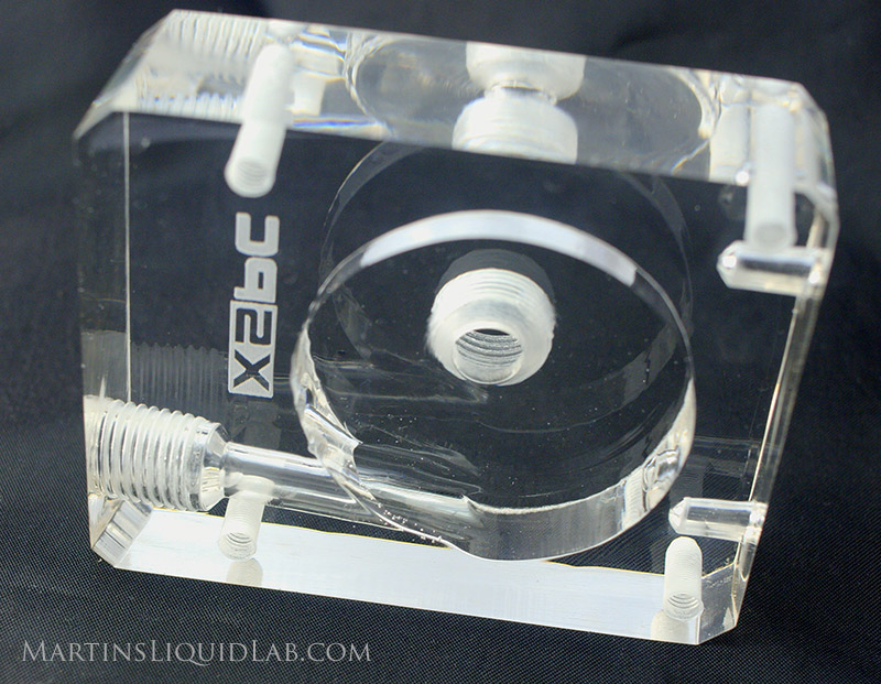 |
 |
7.18 & Taper |
7.00 | Spiral | 7.8 | N/A | Used XSPC Barbs. |
|
XSPC Acrylic Reservoir DDC Top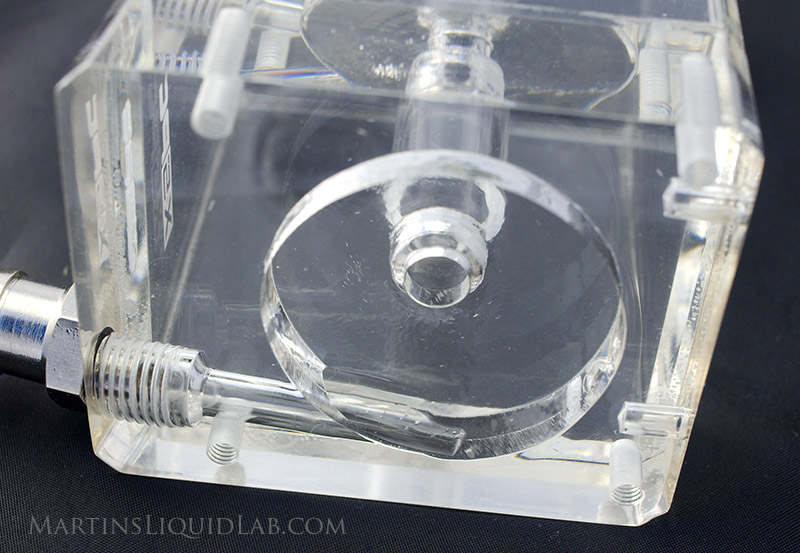 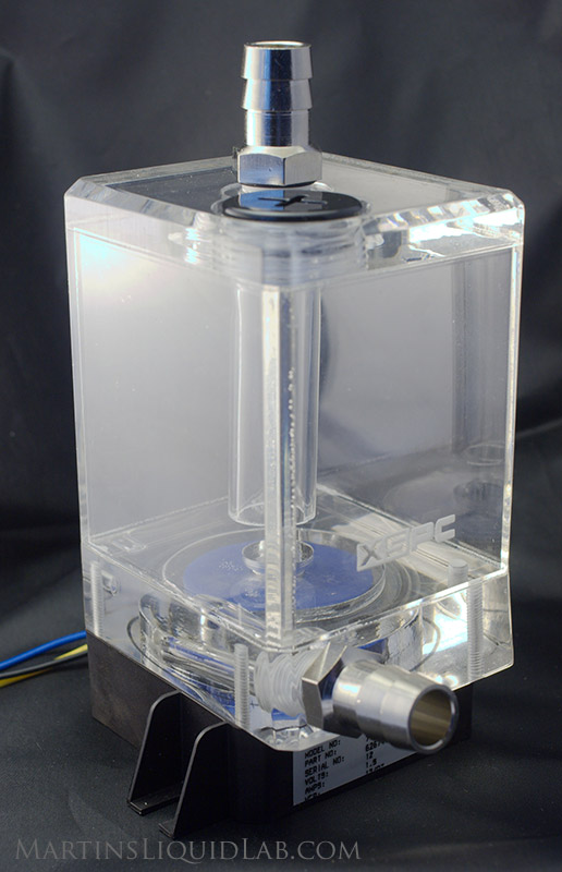 |
 |
7.18 & Taper |
7.00 | Spiral | 7.8 | Excellent See Youtube Video Here |
Had trouble sealing reservoir cap. Used XSPC Barbs. |
|
Stock DDC3.2 or MPC355 Pump stock top |
 |
6.85 | 5.8+- | Semi Spiral |
7.8 | N/A | It's stock.. 3/8" cast barbs! |
Possible Design Tweaks
With that general trend for more restriction and nozzles, I would encourage any tweaks to these already suberb designs to give a little on the flow rate side and tune these pump tops for more pressure. The engineer in me can't help but think there is still a way to make something already great even better..:) I think some of the tops could be improved by tweaks in the following:- Utilize a true "Spiral" shaped volute - this is a little more complicated to design, but it only up front tool path design costs with CNC. A circular volute is not the optimal shape to release flow around the perimeter of the impeller. Water is incompressible (for all practical purposes), so a spiral design with an ever changing radius to provide space for the impeller water coming off is the most efficient shape and allows the entire impeller to do work rather than primarily one side. The semi spiral and relief cut to simulate a true spiral curve do not appear to be nearly as efficient as the full spiral. It actually appears that a regular circular volute shape is doing better than those with relief cuts or two simple curves to simulate a spiral..
- Smaller Inlet Nozzle - I understand the manufacturing simplicity in using a 11.8mm drill bit to drill and then fully tap the inlet hole, but the size exceeds that of the impeller inlet hole, so all you do is introduce yet another sharp entrance loss and this is significant in the pump design.
- Smaller Outlet Nozzle - It appears the nozzle size really is optimally matching that of the impeller and going larger on the outlet port only help flow and going too big may hurt pressure.
- Experiment with tapered and protruding inlets - This is just a theory of mine, but I think something besides a straight tube inlet is beneficial as the water has to turn 90 degrees after entering the impeller. If the jetstream of water is slightly moving towards the perimeter as it enters the impeller, I think that helps reduce that entrance loss. A protruding inlet will also better seal the volute chamber from the inlet....you would just have to experiement and ensure impact is not possible which is difficult with the play possible in all but the stock top (which has cast alignment pins that accept the bolts and).
- Consider using a ball end endmill for the final perimeter cut of the volute. Another theory of mine, but I think if the perimeter catching the water was radius and had a nice smooth spiral transition into the outlet port, you would gain even more efficiency. The cross sectional shape of a circle or pipe is the most efficient shape (least amount of frictional surface area). It appears that very small "details" are key in pump top design, so this may be another detail that returns with performance.
- Consider using recieving studs that extend from the pump top like the stock top. This ensures the top is perfectly aligned with the impeller inlet and eliminates installation errors that can cause imperller to top impact and damage to the pump.
- Smooth finish - roughness coefficients can steal away alot of energy, and nice glass like smooth finish in the perimeter of the pump top and smooth transitions throughout can only be of benefit.
If you have any additional tops to test or corrections in this collection of results please let me know.
Thanks!
Martin